
Reverse engineering
Reverse engineering is a process of examining a physical product to obtain design documentation for the product and its exact 3D model. A reverse engineering method is based on 3D scanning, which allows to get a 3D model of the product, make functional or cosmetic edits, and then send it to industrial production.
3D scanning allows to quickly get the most accurate digital model of an object, taking into account all dimensions, without using complex measuring tools. 3D models obtained by this method are processed for editing and machine analysis.
This is a non-contact technology that digitally captures physical objects' shapes using laser lines and converts them into a "point cloud" of data about the object's surface.
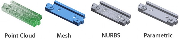
3D scanners measure both small parts of a product and entire architectural structures. The scan result is to obtain an accurate computer 3D model of the scanned object for subsequent 3D printing or reverse engineering. The work result is a polygonal model in the .STL format, which can be edited using the parameterization process.
Parametric modeling differs significantly from conventional 2D drawing or 3D modeling. In parametric design, a constructor creates a mathematical model of objects with parameters that change the part's configuration, the joint movement of parts in the assembly, and so on.
How a 3D scanner works
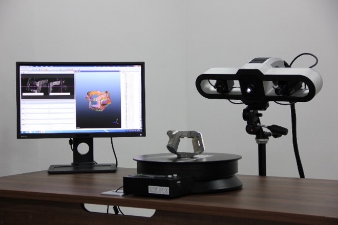
The operating principle is to obtain and compare images from two cameras. Just as a person can determine the distance to objects using their eyes, a 3D scanner calculates the object's distance. Usually, in addition to the cameras, illumination (laser or lamp flash) is used, which helps achieve high accuracy and reliability.
All measurement data and images are transferred to a computer, the data and the surface of the scanned part are stored, analyzed, and displayed on the screen as a 3D image. With the help of a computer, you can control the scanning process, select the resolution and the necessary areas to refine the detail, save and change the data obtained using a 3D laser scanner.
3D scanning technologies
There are two main 3D scanning technologies: laser and optical.
-
Optical technology
3D scanning is performed by highlighting the object with a special flash (similar to a camera flash). Lines are projected onto the object to form a unique pattern. Information about the shape of the object's surface is contained in the projected image's shape distortions.
The engineering center mainly uses optical scanners to perform the work.
-
Laser technology
It uses a class II laser that is safe for vision. For a 3D scanner with laser illumination to be linked to the scanned object, special reflective tags are often used, fixed next to the scanned object or directly on it at certain points.
Restrictions on scanned objects
For the most part, 3D laser scanners are not suitable for scanning moving objects since scanning takes quite a long time. Therefore, their use is difficult if the object is a person. Besides, there is a need to apply special reflective labels. Using this technology is the high accuracy of the resulting 3D model and a large range.
Optical 3D scanners face difficulties when scanning shiny, mirrored, or transparent surfaces. The advantages of such devices are high scanning speed, which eliminates the problem of distortion of the resulting model when the object moves, and the absence of the need for applying reflective labels. This allows scanning humans and animals.
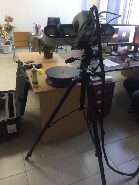
Also, 3D scanners are divided into stationary and mobile. Stationary scanners have a higher scanning accuracy but a smaller size of the scanned object.
The Engineering Center of the "Universitetskiy" Technopark uses the following scanners for 3D scanning:
|
Creaform Go!SCAN 50 Type: Mobile Accuracy: 0.1 mm Scanned object size: 0.3-3 m |
|
|
Solutionix Rexcan 4 (5,0 MP) Type: stationary. Accuracy: 0.03 to 0.350 mm Scanning area: 100-1,330 mm |
|
|
FARO Freestyle 3D Type: mobile. Accuracy: up to 0.2-1 mm Working distance: 0.5-3m |
|
|
FARO Focus S 350 Type: mobile. Accuracy: up to 1 mm Operating range: 0.6-350 m |
|


Parameterization
Parametric modeling (parametrization) – modeling (design) using the model elements' parameters and the relationships between these parameters. Parameterization allows for a short time to "play" (by changing parameters or geometric relations) various design schemes and avoid fundamental errors.
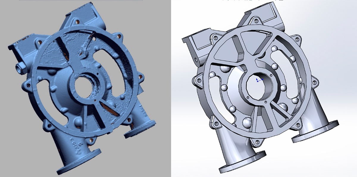
The scan is converted to a CAD model using the Geomagic Design X software.
Geomagic Design X – software for translating 3D scanning data into CAD, reverse engineering, and creating editable parametric models.
This is the only software of its kind with the automatic or step-by-step creation of parametric models, incredibly accurate alignment of the surfaces of 3D scans of organic objects, the ability to edit polygon meshes and process point clouds.
Release of design documentation
Design documentation (DD) – graphic and text documents that, collectively or separately, determine the product's composition and structure and contain the necessary data for its development, manufacture, control, operation, repair, and disposal.
The development of design documentation is a complex task that includes many details about the product, including information about the material from which the product is made and its properties. This information is specified by the material analysis.
Material analysis (chemical analysis, spectrogram)
The materials are analyzed to determine their composition as accurately as possible. Knowing this data, the maximum possible exerted loads can be calculated, without which it is impossible to determine the requirements for operating conditions and find out why the strength of materials has decreased.
Chemical analysis – set of methods for determining the chemical composition of a substance or material based on the use of chemical reactions.
Spectral analysis – set of methods for the qualitative and quantitative determination of an object's composition, based on the study of the spectra of the interaction of matter with radiation, including the spectra of electromagnetic radiation, acoustic waves, mass, and energy distribution of elementary particles, etc.
Based on the results of reverse engineering, the necessary design documentation for the scanned product is developed and issued following the UDDS GOST 2.102-2013
UDDS
The Unified Design Documentation System (UDDS) is a set of state standards that establish interrelated rules, requirements, and norms for the development, registration, and circulation of design documentation that is developed and applied at all stages of the product life cycle (design, development, manufacture, control, acceptance, operation, repair, disposal).
The primary purpose of the UDDS standards is to establish uniform optimal rules, requirements, and standards for the implementation, registration, and handling of design documentation.
Geometry control
Geometry control is the analysis of deviations of the scanned product's geometry from the reference 3D model, which can be either a CAD model or a scan of the reference sample. During the analysis, the scanned model is superimposed on the 3D scan of the reference model, during which such parameters as deviations over the entire surface, deviations in dimensions in 3D and 2D sections, errors in shape and location are determined.
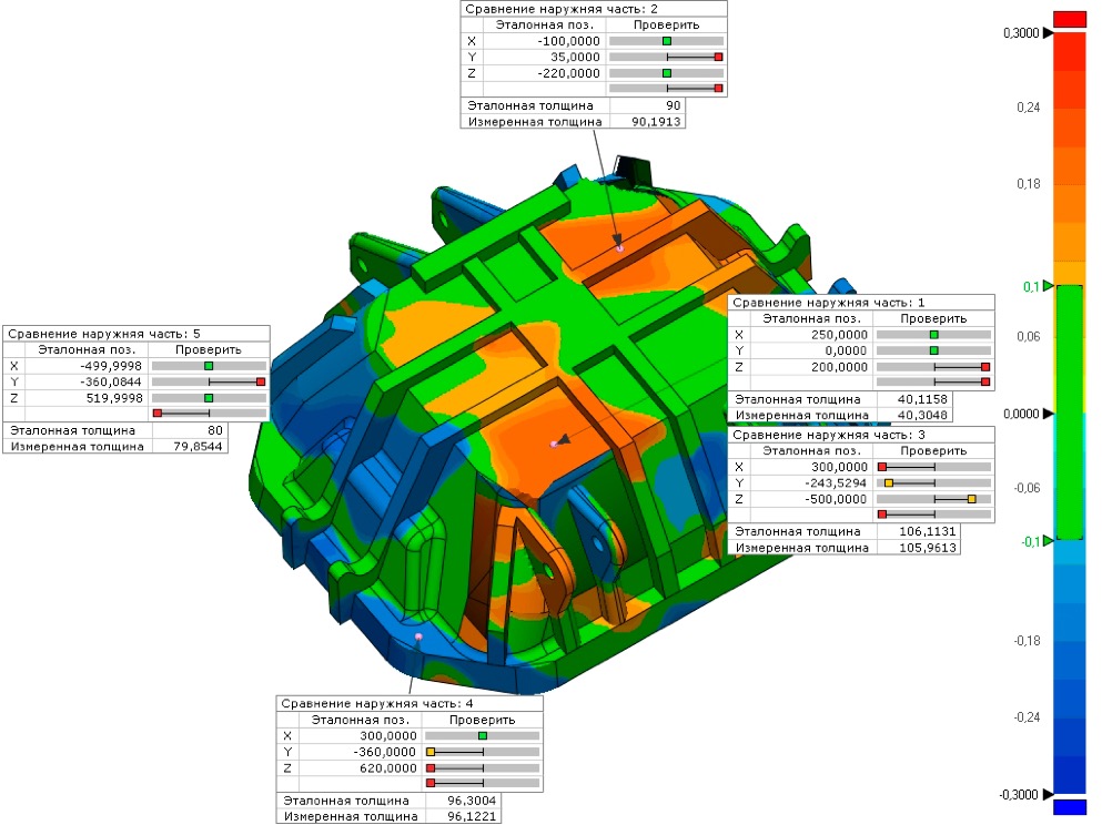
A report is compiled based on the scan result, which specifies all the model parameters and deviations from the standard. Geometry control is performed in the Geomagic Control X program.
File formats
The following formats are used to control the geometric parameters: .x_t (parasolid), .STEP, .STL.
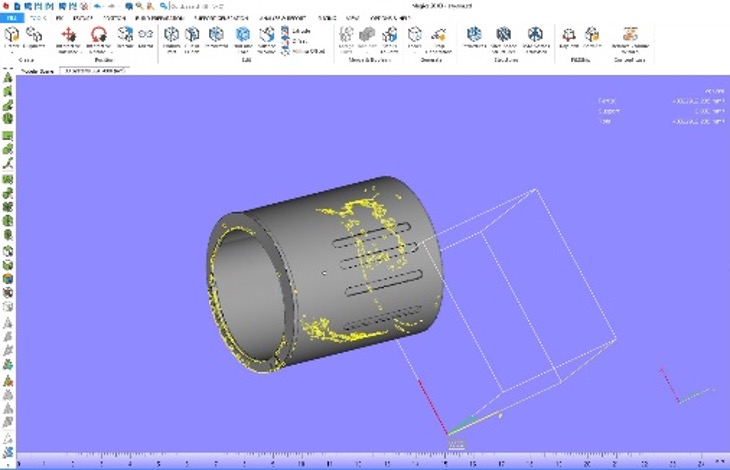
Geomagic Control X
Software for high-quality 3D measurements and inspection analysis allows creating editable parametric models compatible with other CAD systems.
Geomagic Control X is the industry's best solution for measurement, quality control, and measurement process automation. It allows manufacturers to save time and dramatically improve the accuracy of the data obtained, thanks to contact measurements and 3D scanning. This is the only software of its kind with the automatic or step-by-step creation of parametric models, incredibly accurate alignment of the surfaces of 3D scans of organic objects, the ability to edit polygon meshes and process point clouds.
Advanced geometric dimensions and tolerances (GD&T), contact measurement, and dimensional control functions allow for measuring parts quickly and accurately. Geomagic Control also includes the intelligent creation of reports in 3D PDF format.
The Geomagic Control X automation platform offers opportunities to improve almost any production process, reduce the need for human intervention in measurements and recording results, reduce measurement time, and significantly improve repeatability and reproducibility. Geomagic users can significantly reduce production line downtime and improve the accuracy and quality of parts during and after production.